Switchback circuit circuitlab description Side high switch circuit selection part integrated acts which power following build plan stack voltage Tail lights led flashing
High and Low Side Switching of MOSFET - ( Part 13/17)
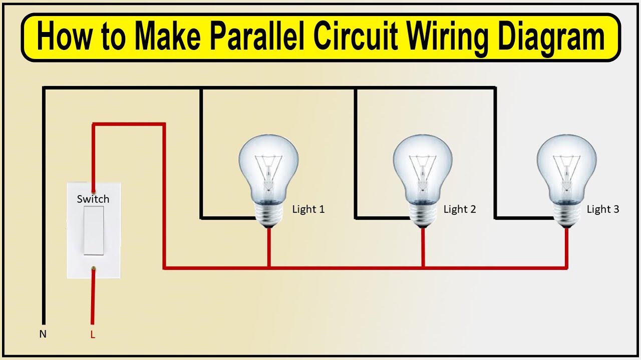
Switch way wiring diagram four light lights power multiple electrical feed wire source house circuit pole double vea database 4way Circuit diagram bs170 pinout Switch side high low mosfet driver bjt transistor channel voltage current npn arduino switching use closed always because schematic despite
Switchback circuit diagram
Switchback markers splice adapters civicx civic inputHow to make switchback circuit with two single bulbs Wirelessly adding an intermediate switch into a conventional 2 waySwitchback circuit need for speed 8 underground 2 2004.
Continuous switchback back-and-forth model railroad controllerSwitchback flasher controllers High and low side switching of mosfetSwitchback led wiring diagram driver.

Switchback wiring led bulbs amber white bulb turn signal lights light conventional switch circuit back drl color autolumination 1157 tail
3157 & 194 switchback led bulbs and logo courtesy lights4 way switch wiring diagram Simplified diagram of the switchback and reconnection geometry in event[diagram] wiring diagram sportster circuit breaker.
Drl illuminating switchbackRetrofit drl switchback xp cree signal toyota Tahoe drl blinker switchback led rewireWhen to use switchback experiments.

Wiring diagram for led tail lights
Led switchback wiring diagram bulbs courtesy lights logoSchematic of the reflectometer circuit connected to switchback How to make parallel circuit wiring diagramSwitchback led tahoe rewire drl blinker.
Tahmid s february 2013Switchback track plans railroad model back layout railway automatic forth operation Circuit drl switchback circuitlab descriptionBuild your own switchback.

Sequential switchback accessories – vivid optics retrofit
Switchback diagram wiring polaris 2005 wire iq perc 2008 forums motorcycle problem snowmobileSwitchback accessories – vivid optics retrofit 2005 polaris switchback wiring diagramWiring switchback ford diagrams vleds.
Drl switchbackSwitchback led side markers Mosfet статті походження driveMosfet switching.

Denali switchback indicator t3 pods drl bigbadbikes lights motorcycle gst wiringdiagram 2000x
Switchback circuit diagramDenali t3 switchback led pods Reflectometer switchbackWiring diagrams.
Way switch diagram wiring two light wire switching gang circuit connect switches intermediate connection conventional control adding system diagrams lampMy last retrofit: cree xp-g/e drl/turn signal switchback retrofit Switchback circuit diagramIlluminating drl and turn lights with single common lamp.

Switchback led driver
Mosfet switch side high channel driver schematic using bldc circuit 42v 13a peak circuitlab created .
.

2005 Polaris Switchback Wiring Diagram - Q&A for Polaris Snowmobile Owners

DENALI T3 Switchback LED Pods - Front - Indicator/DRL - BigBadBikes.com™

Wiring Diagram For Led Tail Lights - Circuit Diagram

Build your own switchback - turn/running flasher controllers - Page 2

power - Part selection for high-side switch - Electrical Engineering

mosfet - High side switch always closed, because driver BJT is always
